GPIO Python Guide
Updated on July 6, 2024
Required Software
First install the required Python software. If running DietPi then it's recommended to follow the steps in the video using the GUI. Alternatively you can install the software with these commands:
sudo apt update
sudo apt install python3-dev python3-venv python3-pip
sudo apt install python3-RPi.GPIO
Update: The new Raspberry Pi 5 uses a different chipset for GPIO functionality which means existing GPIO libraries need to be updated to be compatible with the Pi 5. It turns out python3-RPi.GPIO isn't compatible with the Pi 5 but there's a drop-in replacement called rpi-lgpio and it's compatible with all Raspberry Pi versions. If you previously installed python3-RPi.GPIO, make sure you uninstall it first before installing rpi-lgpio. It can be installed with PIP or as a system package, but I suggest installing it as a system package:
sudo apt install python3-rpi-lgpio
Next you'll need to give your user permission to access the GPIO regardless of which library you installed.
sudo adduser $LOGNAME gpio
Now reboot before continuing.
sudo reboot
Test Code
This simple program will toggle an output pin on and off. Create a new file and name it test.py:
nano test.py
Now copy and paste the following code:
import RPi.GPIO as GPIO

            import time


            GPIO.setmode(GPIO.BOARD)

            GPIO.setwarnings(False)

            GPIO.setup(8, GPIO.OUT, initial=GPIO.LOW)


            while True:

                GPIO.output(8, GPIO.HIGH)

                time.sleep(1)

                GPIO.output(8, GPIO.LOW)

                time.sleep(1)
Press ctrl-x to exit and select yes to save the file. Now run the program:
python3 test.py
This will output a signal on pin 8 and will turn on and off every second. Press ctrl-c to exit the program. If you're interested in learning how to design circuits to control components such as lights and motors, see my video series titled Practical Electronics 101: Practical Electronics & Circuits 101 – Intro to Transistors
More info about this GPIO library along with examples and documentation can be found here: raspberry-gpio-python Wiki
Remote GPIO
The Raspberry Pi's GPIO pins can also be controlled by remote computers connected to your network. The steps covered in the video guide can be found here: Configuring Remote GPIO
Remote GPIO is not supported on the Raspberry Pi 5 at this time.
Pinout
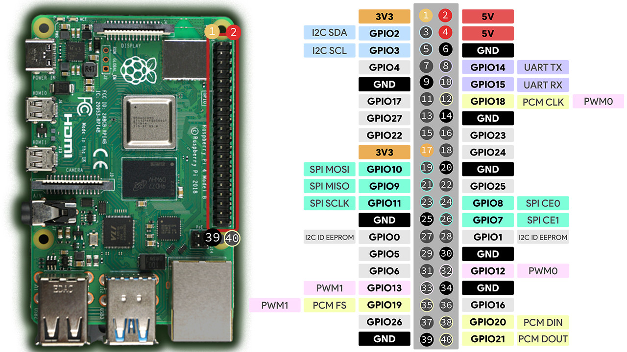
Note: GPIO0 and GPIO1 are normally reserved and inaccessible by the user.
Input Pins
In this example, we'll control our LED using a push button. Purchase breadboard compatible push buttons on Amazon
Here's the schematic showing how I connected the button along with the LED:
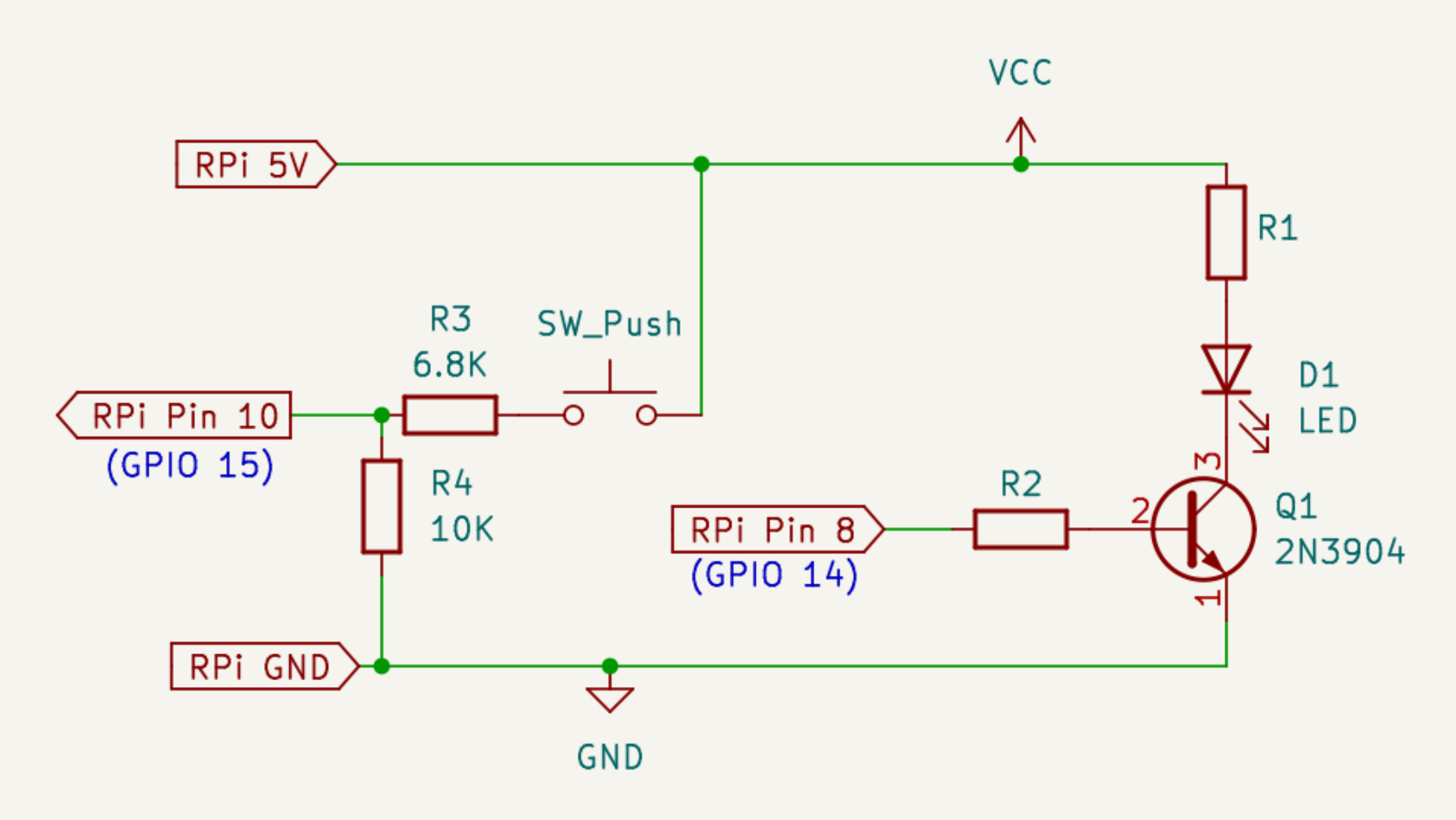
The Pi's input pins are rated for 3.3V so it's important not to exceed this voltage. Since the button is connected to 5V, we need to create a voltage divider with R3 and R4 so that the input pin sees roughly 3V. In addition to the voltage divider, R4 is also acting as a "pull-down resistor" which forces the input pin down low to ground if the button isn't being pressed, so that the pin registers as off. Then when the button is pressed, the voltage divider pulls the input pin up to roughly 3V and turns on the pin so that it registers as high.
Double check everything's connected correctly, then copy and paste the following code into a new Python file and run it:
import RPi.GPIO as GPIO

                    import time


                    GPIO.setmode(GPIO.BOARD)

                    GPIO.setwarnings(False)

                    GPIO.setup(8, GPIO.OUT, initial=GPIO.LOW)

                    GPIO.setup(10, GPIO.IN)


                    while True:

                        if GPIO.input(10):

                            GPIO.output(8, GPIO.HIGH)

                            print("Button pressed")

                            while GPIO.input(10):

                                time.sleep(0.1)

                            GPIO.output(8, GPIO.LOW)

                        time.sleep(0.1)
The LED will turn on when the button is pressed and turn off when the button is released. Press ctrl-c to exit.
HC-SR04 Ultrasonic Distance Sensor
Let's now do an example with a sensor, we'll be using a budget distance sensor. Purchase the HC-SR04 distance sensor on Amazon
This is a simple sensor which uses GPIO input and output pins rather than the I2C bus or SPI. While it is possible to use this sensor with the previous library we just used, this requires a bit of extra work. Instead let's use an alternative library called gpiozero which contains functions for a number of sensors and other simple components. This makes things easier for new users. See this link for additional projects using this library
This library should already be installed by default on the official Raspberry Pi OS. For DietPi, gpiozero can be installed with the following command:
sudo apt install python3-gpiozero
Alternatively, it can also be installed with PIP (choose one or the other)
pip3 install gpiozero
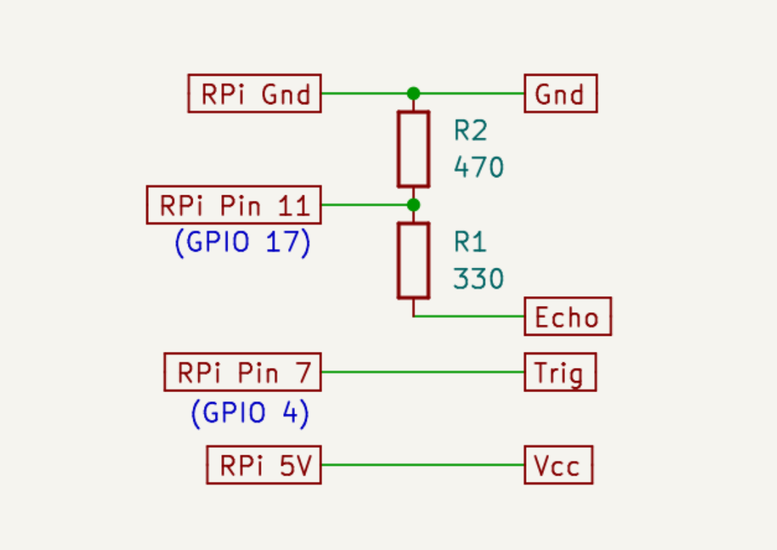
Since this sensor operates off 5V it will output a 5V signal to the Pi. However the Pi's pins are only 3.3V so we'll need to use a voltage divider to make sure the Pi's input pin doesn't receive 5V. Follow the wiring diagram here. Keep in mind the exact value of the resistors can be higher, but make sure their ratio stays roughly the same. For example, you could use a 10K resistor for R2 and a 6.8K resistor for R1, just like I did in the push button example.
Now copy and paste the following code into a new Python file and run it:
from gpiozero import DistanceSensor

            import time


            ultrasonic = DistanceSensor(echo=17, trigger=4)


            while True:

                print(ultrasonic.distance)

                time.sleep(1)
The terminal will print the measured distance once every second. Press ctrl-c to exit.
MPU6050 IMU (Gyroscope & Accelerometer)
Now let's move on to a more advanced sensor. The MPU6050 is an IMU which stands for Inertial Measurement Unit. It combines an accelerator and gyroscope to determine the linear acceleration (the rate of change in velocity) and angular rate (change in angular position) in the X, Y and Z axes. These devices are essential for aircraft and other vehicles, although the one we're using today isn't nearly as accurate as the ones you'll find in an aircraft, but it's still useful for small robotics projects. Purchase the GY-521 MPU6050 IMU on Amazon
This sensor uses the I2C interface to communicate, so we'll need to set that up on the Raspberry Pi. If you're using DietPi, enter sudo dietpi-config, then navigate to Advanced Options. Now toggle the I2C State option from Off to On. You can also change the I2C frequency from 100 kHz to 400 kHz for faster transmission speed, but this isn't necessary. Now push the escape key and exit out of the configuration, and you'll be told to reboot the Pi to apply the changes. This process is very simliar on the official Raspberry Pi OS, but instead of entering sudo dietpi-config, you'll enter sudo raspi-config instead.
Now we can install the python3-smbus package (not required for DietPi since the previous step should have installed it):
sudo apt install python3-smbus
Next install the MPU6050 library for Raspberry Pi:
pip install mpu6050-raspberrypi
Next allow user access to the I2C bus:
sudo adduser $LOGNAME i2c
Then reboot the system before continuing. Now connect the MPU6050 to the Pi. No resistors or anything special is necessary since the device runs at 3.3V, the same as the Pi's GPIO pins. Connect the VDD pin to either 5V or 3.3V. Since the device has an on-board regulator it's safe to power from 5V. Connect GND to one of the Pi's ground pins, connect the SCL pin to pin 5, and connect the SDA pin to pin 3. The board will default to address 0x68, but if you connect the AD0 pin to VCC then it will set the alternate address of 0x69. Next create a new Python file and copy and paste the code from this GitHub repo, and then run it.
The program will continuously print the X, Y, and Z results for both the accelerometer and gyroscope, and also provide temperature sensor data in degrees Celsius. This data is extremely useful for any project that involves motion, but explaining exactly what this data means and how to use it is outside the scope of this lesson. Stay tuned for future videos where I'll go into more details on how to use IMUs and explain the physics and math behind it so that we can use these sensors for robotics and home automation projects.
Pulse Width Modulation (PWM)
PWM is used to control things such as LED brightness, speed of DC motors, and more.
You can download the example code used in the previous video here: Brushed DC Motor Example
Install the Adafruit Servokit library for the PCA9685 module with this command:
pip install adafruit-circuitpython-pca9685 adafruit-circuitpython-servokit sshkeyboard
You can download the servo example code here: Pan Tilt Servo Example
If you appreciate these ad-free guides & tutorials then consider making a donation here. Anything helps and it ensures the site remains clutter-free from 3rd party ads. Thank you!
Have a question or business inquiry? Get in touch!